Radiative Transfer Equation
Published:
Long time no see. After a tiring semester, I finally have the chance to update posts. Though there is much research progress to be talked about, it demands some more time to collect my thoughts about it. So this post will be a rather simple introduction to a famous equation in both physics and computer graphics, the radiative transfer equation (RTE).
Overview
Clouds, fog, muddy water and similar media can scatter light, and they are called participating media. Rendering these media certainly entails how light propagates and changes in them. This is also called volume rendering.
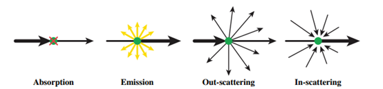
Generally, there are 4 types of events: light is emitted from the media, light is absorbed by other particles and its energy turns into something else, e.g., heat, light hits a particle and deviates from its original direction, and other particles hit light to change its direction. These types are summarized and termed as
- emission,
- absorption,
- out-scattering, and
- in-scattering.
The rest parts will elaborate on these phenomena one by one, and eventually arrive at the all-encompassing form of RTE.
Emission
Emission refers to the phenomenon that the media themselves can let out light, or provides gains in energy then rays pass through them. In a uniform media, it can be asserted that the radiance increases linearly with path length. So we have,
\[\frac{\mathrm{d}}{\mathrm{d}t}L(t)=\epsilon(t).\]When it comes to a 3D, anisotropic situation, we need a representation that can fit the flexible locations and properties of the media, which is
\[(\vec{\omega}\cdot \nabla_e)L(\boldsymbol{x}\rightarrow\vec{\omega})=\mu_a(\boldsymbol{x})L_e(\boldsymbol{x}\rightarrow\vec{\omega}),\]where $(\vec{\omega}\cdot \nabla_e)$ denotes the directional derivative for light passing location $\boldsymbol{x}$ in direction $\vec{\omega}$, $L(\boldsymbol{x}\rightarrow\vec{\omega})$ the radiance at $\boldsymbol{x}$, $\mu_a(\boldsymbol{x})$ the absorption coefficient, and $L_e(\boldsymbol{x}\rightarrow\vec{\omega})$ the radiance emitted from the media.
Absorption
It is represented by basically a negative form of emission, still a linear relationship with path length.
\[(\vec{\omega}\cdot \nabla_a)L(\boldsymbol{x}\rightarrow\vec{\omega})=-\mu_a(\boldsymbol{x})L(\boldsymbol{x}\rightarrow\vec{\omega}).\]One thing worth further discussion is the absorption coefficient $\mu_a$. Its unit is, by standard, $\text{m}^{-1}$, the reciprocal of distance. So it is actually the probability distribution of the radio of absorption along a certain line. By definition, it seems that it should be a function upon both location and direction. The common practice, however, is to regard it as merely dependent on location, so that each voxel can feature a pre-calculated value for simplification.
Out-scattering
Out-scattering refers to particles hit light to make it change its direction, leading to reduction in the radiance along the original direction.
\[(\vec{\omega}\cdot \nabla_o)L(\boldsymbol{x}\rightarrow\vec{\omega})=-\mu_s(\boldsymbol{x})L(\boldsymbol{x}\rightarrow\vec{\omega}),\]where $\mu_s$ is the scattering coefficient. Typically, in RTE we don’t lay much emphasis on radiance in any direction except the observed $\vec{\omega}$. Therefore, the effects of out-scattering and absorption are combined to form the extinction part of the final equation, i.e.,
\[\begin{aligned} (\vec{\omega}\cdot \nabla_{ex})L(\boldsymbol{x}\rightarrow\vec{\omega})&=-(\mu_a(\boldsymbol{x})+\mu_s(\boldsymbol{x}))L(\boldsymbol{x}\rightarrow\vec{\omega}), \\ &=-\mu_{ex}(\boldsymbol{x})L(\boldsymbol{x}\rightarrow\vec{\omega}) \end{aligned}.\]In-scattering
Contrary to out-scattering, in-scattering means an increase in radiance along the observed direction due to interaction with other particles.
\[(\vec{\omega}\cdot \nabla_o)L(\boldsymbol{x}\rightarrow\vec{\omega})=-\mu_s(\boldsymbol{x})L_i(\boldsymbol{x}\rightarrow\vec{\omega}).\]Since scattering contributes to an increase in radiance in the desired direction, its coefficient cannot be simply ignored. It adheres to one’s intuition that, this increase effect results from all directions in a 3D space. So denote the solid angle of all possible lights as $\vec{\omega}^\prime$, we need spherical integral to calculate $L_i$, i.e.,
\[L_i(\boldsymbol{x}\rightarrow\vec{\omega})=\int_{\Omega_{4\pi}}p(\boldsymbol{x}, \vec{\omega}^\prime\rightarrow \vec{\omega})L(\boldsymbol{x}\leftarrow\vec{\omega}^\prime)\mathrm{d}\vec{\omega}^\prime,\]where $p(\boldsymbol{x}, \vec{\omega}^\prime\rightarrow \vec{\omega})$ refers to the phase function that describes the distribution of scattering of a certain point in any direction. It is usually anisotropic, and can vary depending upon how we decide to describe the scattering in specific cases. More on that later.
In sum, these 4 components together form the ultimate representation of RTE, written as
\[\begin{aligned} (\vec{\omega} \cdot \nabla) L(\mathbf{x} \rightarrow \vec{\omega})&=-\underbrace{\sigma_a(\mathbf{x}) L(\mathbf{x} \rightarrow \vec{\omega})}_{\text {absorption }}-\underbrace{\sigma_s(\mathbf{x}) L(\mathbf{x} \rightarrow \vec{\omega})}_{\text {out-scattering }}+\underbrace{\sigma_a(\mathbf{x}) L_e(\mathbf{x} \rightarrow \vec{\omega})}_{\text {emission }}+\underbrace{\sigma_s(\mathbf{x}) L_i(\mathbf{x} \rightarrow \vec{\omega})}_{\text {in-scattering }} \\ &=-\underbrace{\sigma_{ex}(\mathbf{x}) L(\mathbf{x} \rightarrow \vec{\omega})}_{\text {extinction}}+\sigma_a(\mathbf{x}) L_e(\mathbf{x} \rightarrow \vec{\omega})+\sigma_s(\mathbf{x}) L_i(\mathbf{x} \rightarrow \vec{\omega}) \end{aligned}\]